

Installing a transmission-mounted PTO
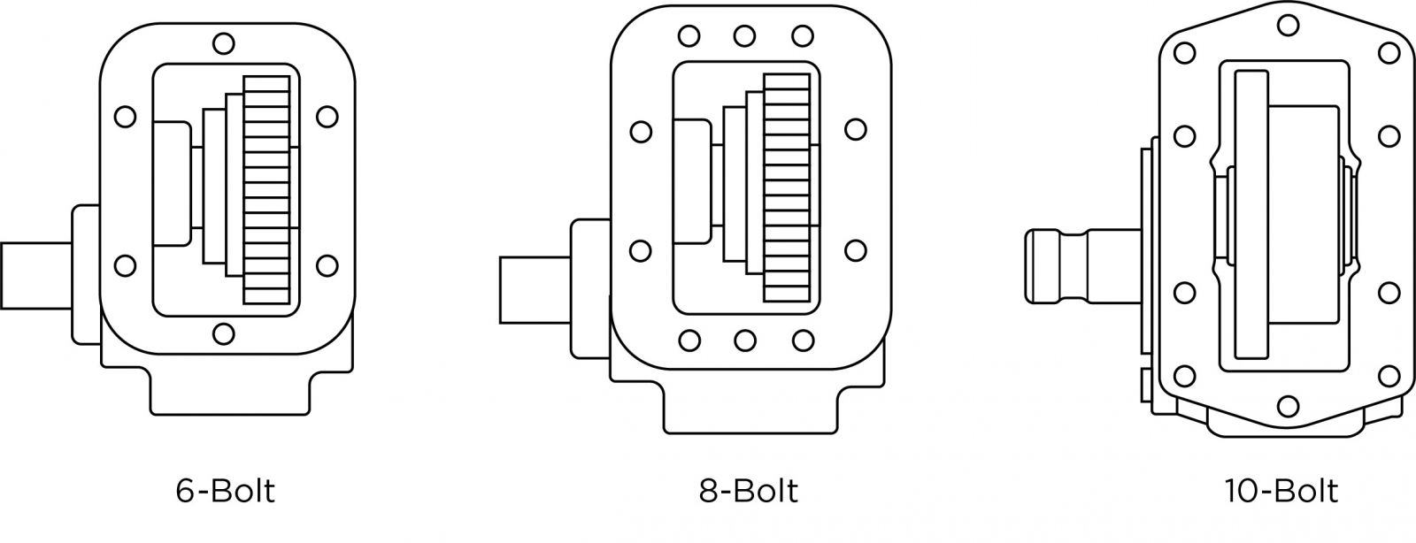
The majority of power take-offs (PTOs) used today in the North American market are on the side or bottom opening. The Society of Automotive Engineers (SAE) has set the standard for 6-bolt and 8-bolt patterns, and there are also non-standard 6-bolt and 10-bolt patterns. These openings refer to the number of fasteners used to attach the PTO to the transmission. A 10-bolt opening is exclusive to automatic transmissions manufactured by Allison, Caterpillar, and Ford.
Many problems can be avoided by exercising extreme care during the installation procedure.
Follow instructions as to where warning and safety labels are to be placed and review the following steps before starting the installation process:
1. Before installation, listen to the engine and transmission while it is running so you can distinguish any unusual sounds.
2. Make sure the engine is off and remove the keys.
3. For manual transmissions, drain the transmission fluid. For automatic transmissions, do not drain fluid, but be prepared for some seepage.
4. Then, while under the truck, remove the cover plate and inspect the drive gear for correct backlash manufactured into transmission gear sets.
5. Check the mounting surface of the transmission and the PTO drive gear in the transmission for anything that could cause problems (nicks or burrs).
6. When the PTO cover is off, prepare to clean the mounting surface by placing a clean shop towel on the opening to eliminate debris from going into the transmission. It is recommended to also clean the bolt holes. Items necessary for cleaning:
- Shop towel
- Wire brush
- Putty knife (optional)
7. Open the PTO box to inspect the unit and make sure you have all the mounting hardware.
8. Before installing the PTO, the installer should be familiar with the unit’s backlash .006 in.–.012 in. (or .15 mm.–.30 mm.) between the PTO input gear and the transmission drive gear. Rock transmission gears by hand to get a feel for gear backlash.
Note: Before installing a PTO, use a dial indicator to check the backlash.
9. Install the studs until the barrel of the stud is even with the transmission pad. Typically, this requires a torque limit of 30–35 lbs.ft. (6-bolt opening), 45–50 lbs.ft. (8-bolt opening), or 40–45 lbs.ft. (10-bolt opening). However, it is recommended that you check your installation manual for proper torque limits.
10. Remove the shift cover or inspection cover plate from the PTO to rock input gear with the transmission PTO drive gear to get the feel of backlash, which is helpful when fitting PTO to transmission.
11. Place the gasket or shim from your kit over the studs, a thin coat of transmission oil on the gasket can help to hold it into place during installation. Double check your mounting instructions, as some newer transmissions (Allison and Fuller) have been designed with a controlled compression-type gasket and a predetermined backlash, which is to eliminate the need to check backlash.
12. Check the backlash; the goal is .006 in.–.012 in. As a reference, the thin gasket measures .010mm, and when compressed, it is .006 in., and the thick gasket measures .020 in., and when compressed, it is .012 in. Do not stack more than four gaskets or shims together. On Allison transmissions (AT-500, MT-600, HT-700, 1000, 2000, and 2400 Series only), use a single .030 in. gasket or shim.
Note: Never use silicone-type sealants on the transmission's PTO mounting surface. A proper backlash cannot be attained, and you may need to adjust the amount of gasket or shims to achieve the proper backlash.
13. Torque all fasteners to the appropriate settings to eliminate possible leaks, which could lead to PTO and or transmission damage.
14. Depending on the type of PTO used, place the shift cover or inspection plate on the PTO and torque nuts to specified requirements.
15. There may be a case where a gear adapter is required, remember the backlash must be set at two locations. First, set the correct backlash between the adapter and PTO and set the gaskets aside. Second, mount the adapter with proper backlash to the transmission. Then, mount the PTO to the adapter with the correct gasket which you set aside.
16. Start the truck engine (with PTO and transmission in neutral) for only a few seconds and listen for any unusual noises. Keep the PTO and transmission running time as short as possible until the transmission is refilled with transmission fluid.
17. Beware and stay clear of any rotating components. A whining noise that elevates with the RPM indicates a PTO is mounted too tight, which would require an additional gasket; stop the engine, repeat the process using a dial indicator to check your backlash, and add a gasket. A clattering noise indicates the PTO is mounted too loose, so it would require removing a gasket; stop the engine, repeat the process using a dial indicator to check your backlash, and remove a gasket. Afterward, repeat this test with PTO engaged.
Please note:
- A PTO will not always make these noises.
- Do not adjust backlash by noise alone, always visually check backlash and use a dial indicator.
- Sometimes, filling the transmission with fluid is the only way to reduce the noise.
RELATED: Troubleshooting: PTO noise
18. Refill the transmission with the manufacturer’s approved fluid and the proper amount, then run the engine for five to 10 minutes to check for leaks. With the engine off, re-torque the fasteners to the appropriate settings.
19. Install the appropriate shifter kit components, including the supplied PTO shift indicator light. On air systems only, the pressure protection valve requires the main tank pressure to exceed 65 PSI to operate the PTO system.
20. If direct mounting a hydraulic pump weighing over 40 lbs. (weight includes fittings, oil, and unsupported hose sections), exceeding 12 in. in length, tandem or multiple section pumps, a high vibration engine, or off-road vehicles, a rigid four-point support bracket needs to be installed. The bracket should be attached to the rear of the pump and to the transmission to support the pump and inhibit movement in all directions.
21. Add the PTO to the regular inspection routine of the application, look for leaks, and re-torque all mounting bolts, nuts, and cap screws on a regular basis.
RELATED: How to use the PTO Builder
Additional information:
WATCH: Step-by-step video on installing the A20 Series PTO.
It is important to select the proper PTO to match up with both the transmission and application requirements. Muncie has a web-based PTO builder or Quick Reference Catalog for help in correct application selection.
Follow the manufacturer’s recommended installation instructions that are sent with the completed PTO unit. Pull the PTO unit, gasket, and fastener kits out to inspect for defects or damage before installing them.
View all PTO literature, including installation instructions, here
Additional reference material: Understanding Power Take-off Systems (TR-G94-01 Rev.10-17).
Muncie Power Products has a customer service department that puts people first. If you have any questions or concerns, reach out for questions: 1-800-367-7867 or 765-284-7721.