

Prevent the Most Common Dump Pump Failure
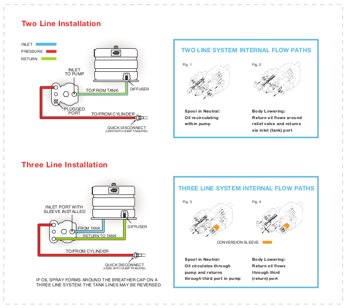 A dump pump, as used on a typical dump truck in North America, is a combination of a hydraulic pump, a pressure relief valve, and a directional control valve in one housing. The pump also has a pressure port that connects to the hydraulic cylinder and a larger port connected to the hydraulic reservoir. This is the most common method of connecting the dump pump to the rest of the system, and is called a 2-line system, as shown in Figures 1 and 2.
How does it operate? When the pump input shaft is rotated, the gears create a low-pressure area that is filled with fluid from the reservoir. As the gears continue to rotate, they mesh at the pressure side. With the directional control in neutral, the oil circulates from the pressure side of the pump back to the inlet side, circulating within the pump chamber. When the directional valve is shifted to the raise position, the passage to recirculate oil is blocked, forcing the fluid out of the pressure port to extend the cylinder. If the pressure reaches the set point of the relief valve, it opens, returning the oil to the inlet side of the pump.
When the directional valve is moved to the lower position, the oil is allowed to return from the cylinder, passing back to the inlet side of the pump, and returning to the reservoir.
This system functions effectively as long as the pump is not operated too long with the oil circulating within the pump. If the PTO is left engaged for an extended period of time, such as driving away from the site, the pump gears continue circulating approximately a cupful of oil.
As it does, it is heated by friction in the pump and hydraulic slippage. Eventually, the temperature gets high enough to damage the pump. This condition is simple to diagnose because the pump housing looks burned, often blistering or discoloring the paint.
There is a simple solution.
Dump pumps typically have a third port designed to redirect oil to the reservoir rather than circulating within the pump. Circulating the oil through the reservoir allows the oil in the pump to remain at acceptable temperatures, preventing failure. This is called a 3-line system, see Figures 3 and 4. This is usually listed as an option on company price sheets or literature.
Using the third line, or a separate return line to the reservoir, requires two steps. First, remove the inlet or suction hose connection from the pump and insert the conversion sleeve as shown in Figures 3 and 4. Second, remove the plug from the third port and install a separate return line connecting to the reservoir below the oil level, preferably with a diffuser.
RELATED: Wet Line Kits for Dump Trailers: Two-line vs. Three-line
Circulating the oil through the third port to the reservoir allows the oil in the pump to remain at temperatures that prevent failure. A 3-line system is an affordable option that prevents most dump pump failures.